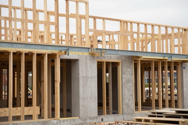
When a beam, whether steel, concrete or timber, transfers its load into a masonry wall, the stress concentration at the bearing point can crush or crack the masonry beneath. A padstone solves this by spreading that point load over a larger surface area, keeping stress within safe limits for the blockwork or brickwork below.
Padstones are a small but frequently overlooked structural element. Omitting them, undersizing them, or using the wrong material is a common cause of cracking around lintels and beams, sometimes appearing months or years after a beam was installed.
Why Padstones Are Needed
The concrete blocks used in most houses are typically rated at 2.9–7.3 N/mm² (depending on block type), and even a high-strength aircrete block is rated at 7.3 N/mm².1 A loaded steel beam in a house can deliver several tens of kilonewtons at each end bearing. Without a padstone, that load passes through only the end section of the steel onto the masonry, a contact area that can be as small as 100 mm × 100 mm. The resulting stress easily exceeds the blockwork’s capacity.
A padstone made from dense precast concrete (commonly manufactured to around 40–50 N/mm²) or Class B engineering brick (compressive strength at least 75 N/mm²) distributes that same load over a larger footprint, reducing the stress to within safe limits.2
The padstone also provides:
- A flat, level, mortar-bedded seating surface for the beam
- Protection against local spalling of the inner leaf when the beam deflects under load
- A defined bearing zone that can be inspected and recorded
Concrete vs Engineering Brick Padstones
Two materials dominate UK padstone practice:
| Type | Compressive Strength | Cost (each) | When Used |
|---|---|---|---|
| Precast dense concrete block | 40–50 N/mm² | £8–£35 | Standard choice for most steel and timber beams |
| Engineering brick (Class B) | ≥ 75 N/mm² | £0.65–£2 per brick | Light loads, smaller bearings, historic masonry repairs |
| Engineering brick (Class A) | ≥ 125 N/mm² | £2–£3 per brick | Heavy loads or aggressive exposure |
| In-situ concrete pad | 25–35 N/mm² | Materials only (labour varies) | Large or irregular bearings; formed in shuttering |
| Steel bearing plate | N/A (distributes load) | £15–£60 | Under very heavy steel columns or beams |
For comparison, a 440 × 215 × 100 mm precast C40/50 padstone lists at £32.08 including VAT at Robert Price.3 Selco lists a 65 mm Class B engineering brick at £0.66 including VAT.4 Solid red Class B engineering bricks sold through B&Q cost £192 for a pack of 100, about £1.92 each.5 A solid blue Class A engineering brick lists at £2.36 including VAT at Lords Builders Merchants.6
In the UK, a Class A engineering brick has a compressive strength of at least 125 N/mm² and water absorption below 4.5%, and a Class B at least 75 N/mm² and below 7%.7 Engineering bricks are often used in pairs or multiples, bedded in a strong cement mortar, to achieve the required bearing area. Their high density and low water absorption also resist moisture wicking in damp-prone locations.
Precast concrete padstones are the most common choice for domestic beam insertions. They are supplied in standard sizes (see below) and can be ordered from builders’ merchants or structural suppliers. They are bedded in full-bed cement mortar before the beam is set on top.
Sizing Padstones
The padstone must be large enough to reduce the bearing stress to within the allowable capacity of the masonry beneath. Sizing is a structural engineering calculation, but the following rules of thumb give a starting point for standard domestic scenarios:
Minimum bearing length (the dimension along the beam span) is typically 100–150 mm for lintels and beams in domestic masonry. Approved Document A’s simple guidance for lintels assumes a bearing length of 150 mm, reduced to 100 mm where the clear span is 1.2 m or less.8 For heavier steel beams (UB 203 and above), 150–200 mm bearing is common.
Padstone footprint must be sized so that: load ÷ padstone area ≤ allowable bearing stress of the masonry below. Structural engineers use BS EN 1996-1-1 (Eurocode 6) and the UK National Annex for masonry design.9
Typical precast padstone sizes stocked by UK suppliers:
| Padstone size (L × W × H, mm) | Typical application |
|---|---|
| 215 × 140 × 100 | Light timber joists and lintels |
| 440 × 140 × 100 | Standard domestic steel lintels and beam ends |
| 440 × 215 × 100 | Heavier beams over door/window openings |
| 440 × 215 × 140 | Larger UB sections in loft conversions |
| 440 × 215 × 215 | Steel beams with high point loads |
| 600 × 215 × 215 | Heavy structural beams in extensions |
Stowell Concrete, for example, makes 440 × 215 × 140 mm and 440 × 215 × 100 mm padstones.2
For a standard loft conversion ridge beam or an RSJ replacing an internal wall in a 1930s terrace, a 440 × 215 × 140 mm or 440 × 215 × 215 mm precast padstone is typically specified. Your structural engineer should confirm this.
Spread Bearings and Alternative Solutions
Where an inner leaf is thin, or the masonry below is in poor condition, a padstone alone may not be sufficient. Options include:
Spreader plates: galvanised or grade S275 steel plates welded to or placed beneath the beam end. These spread load over a wider area than a padstone and are sometimes preferred in heavily loaded commercial scenarios.
Column bases: for point loads from posts or columns, a reinforced concrete column base or proprietary steel base plate is used rather than a padstone.
Joist hangers: where timber joists or beams meet a masonry wall, proprietary hangers to BS EN 845-1 (e.g. Simpson Strong-Tie or MiTek) can carry them instead of building the ends into the wall.8 A masonry hanger is built into a bed joint, so its load still passes into the wall by bearing and the masonry beneath it needs the same care as under a padstone.
Wall Plates
A wall plate is a horizontal timber member (typically 100 × 75 mm or 75 × 50 mm regularised treated softwood) bedded in mortar on top of an inner leaf or ring beam. It distributes concentrated rafter, truss or joist loads along the wall line, and provides a fixing surface for the structural members above.
Wall plates are standard practice in traditional roof construction:
- At eaves level: on top of the inner leaf of the cavity wall, supporting rafters or truss tails
- At floor level: where joists are to be fixed to a wall (in some masonry details)
Wall plates must be:10
- Preservative-treated where the risk calls for it, following BS 8417:2024 (timber preservation), which sets the treatment by use class
- Bedded level on a full bed of mortar
- Kept clear of the cavity and away from the outer leaf
- Continuous along the wall where possible, with scarf joints staggered
Wall Plate Straps
One of the most important and most frequently missed details in UK domestic construction is the holding-down strap connecting wall plates to the masonry below. Approved Document A, the guidance on Building Regulations Part A, calls for them to resist wind uplift: vertical strapping at least 1 m long at eaves level, at intervals of no more than 2 m.8 They can be left out only where the roof is pitched at 15° or more, is tiled or slated, is of a type known locally to resist wind gusts, and has its main timbers spanning onto the wall at no more than 1.2 m centres.8
Straps are galvanised steel (commonly 30 mm wide and at least 1 m long). They are fixed to the wall plate or rafters and down the inner face of the inner leaf at no more than 2 m centres.8
| Strap requirement | Spacing |
|---|---|
| Holding-down straps (wall plate to masonry) | Max 2.0 m centres |
| Rafter ties (rafter to ceiling joist, where not trussed) | At every rafter |
| Gable wall straps (to anchor roof to gable) | Max 2.0 m centres along the roof slope |
Omitting holding-down straps where they are needed is a serious structural deficiency. In high wind exposure zones (exposed coastal and upland areas), strap spacing may need to be reduced, refer to BS EN 1995-1-1 and the Timber Research and Development Association (TRADA) guides.
Used with Steel and Timber Beams
The padstone sits below the beam end, the beam sits on the padstone, and, in most domestic steel installations, a packing plate or thin grout bed levels the beam perfectly. For timber beams, the padstone is usually topped directly by the beam end without packing.
The sequence for a standard RSJ installation:
- Build the masonry to the correct height, incorporating the padstone in the bed joint (or bedding the padstone on top of the masonry as a separate unit).
- Prop the existing structure.
- Cut the wall opening and set the padstone(s) level, with full mortar bedding.
- Lower the steel onto the padstones (two operatives minimum; mechanical assistance for heavy sections).
- Allow the mortar and any packing to gain enough strength before removing props, for the period your engineer specifies (often at least 48 hours, and longer in cold weather).
The padstone is always specified by the structural engineer who designs the beam. If a padstone size, specification or bearing length is not stated in the structural engineer’s drawings or calculations, ask before proceeding.
References (10)
Figures in this note were checked against the sources below on 30 September 2026. Superscript numbers in the text point to them. Every source the site cites, by topic.
- 1technicalsupplier figureH+H UK, a data sheet.RN-HU3368Celcon High Strength Grade aircrete block. Compressive strength 7.3 N/mm2, thermal conductivity 0.18 W/mK, dry density 730 kg/m3, widths 100 mm to 355 mm. Covered for beam and block floor infill by BBA certificate 05/4275, which applies to all Celcon grades.
- 2technicalsupplier figureStowell Concrete, guidance.RN-IPXPQXA precast concrete maker's padstone product page. It gives the compressive strength its padstones are made to and the sizes it produces.
- 3costsupplier figureRobert Price Builders' Merchants.RN-IYXDPSA price, true at 2026-09. A builders' merchant's product page for a 440 x 215 x 100 mm precast C40/50 concrete padstone with its price including and excluding VAT. It sits inside the note's padstone price range.
- 4costsupplier figureSelco Builders Warehouse.RN-O1FQU0A price, true at 2026-09. A builders' merchant's product page for a single 65 mm red Class B engineering brick, priced including and excluding VAT. It sets the low end of the Class B row.
- 5costsupplier figureB&Q (sold by Materials Market).RN-6DUCABA price, true at 2026-09. A retailer's product page for a pack of 100 solid red Class B engineering bricks and its pack price. It sets the high end of the Class B row at about £1.92 a brick.
- 6costsupplier figureLords Builders Merchants.RN-H6VWVHA price, true at 2026-09. A builders' merchant's product page for a single solid blue Class A engineering brick, £2.36 including VAT and £1.97 before it. It supports the Class A row.
- 7technicalsupplier figureWienerberger UK, guidance.RN-81XA5UManufacturer page for engineering bricks. It gives the Class A and Class B compressive strength and water absorption limits from the UK National Annex to BS EN 771-1.
- 8technicalvery strongMinistry of Housing, Communities and Local Government (GOV.UK).RN-Z6AXUWThe full Approved Document A PDF, which carries the deemed-to-satisfy tables a domestic project is checked against. Section 2E covers foundations of plain concrete: paragraph 2E3 gives the recommended minimum widths of strip foundations in Table 10, keyed to ground type and total load of loadbearing walling per linear metre. Table 10 sets, for rock (not inferior to sandstone, limestone or firm chalk, requiring at least a pneumatic or mechanically operated pick to excavate), a width equal to the width of the wall at every load. For medium dense gravel or sand (requires a pick to excavate, a 50mm square wooden peg hard to drive beyond 150mm) and for stiff clay or stiff sandy clay (can be indented slightly by the thumb), the minimum widths are 250mm at 20 kN per linear metre, 300mm at 30, 400mm at 40, 500mm at 50, 600mm at 60 and 650mm at 70. Firm clay and firm sandy clay (thumb makes an impression easily) start at 300mm. The document also covers minimum depth of strip foundations, wall thickness rules for residential buildings up to three storeys (paragraph 2C10 covers internal loadbearing walls in brickwork or blockwork), buttressing, lateral support by floors and at roof level, interruption of lateral support, wall cladding in Section 3, and Section 5 on reducing sensitivity to disproportionate collapse with the building consequence classes.
- 9technicalstrongBSI, guidance.RN-T0PRVQBSI catalogue page for BS EN 1996-1-1. It confirms the standard is Eurocode 6, the general rules for designing masonry structures.
- 10technicalstrongBSI (British Standards Institution), a standard.RN-1YSDSKSTATUS: CURRENT. BS 8417:2024 published 15 August 2024, superseding BS 8417:2011+A1:2014. Gives recommendations and guidance for the preservative treatment of wood to provide protection against biodeterioration in end-use situations. Covers solid wood and glued laminated wood (Glulam); excludes wood-based panel products, physically or biologically modified wood, and curative treatments. It takes into account the natural durability and treatability of the wood, the use class as defined in BS EN 335, and the desired service life, and recommends penetration and retention levels for different timber components. This is the source of the Use Class 2 / Use Class 4 language on treated batten and fence post labelling, and of the stated desired service lives (30 or 60 years) manufacturers quote. Treatment certificates quoting BS 8417:2011 predate the 2024 rewrite.
-
High Strength Grade Aircrete Blocks, H+H UK, accessed 30 September 2026. hhcelcon.co.uk
-
Padstones 50.0 N/mm2, Stowell Concrete, accessed 30 September 2026. stowellconcrete.co.uk
-
Pre-cast Concrete Padstone C40/50 (440mm x 215mm x 100mm), Robert Price Builders’ Merchants, accessed 30 September 2026. Priced at 2026-09 and left there. robert-price.co.uk
-
65mm Sandown Red Class B Engineering Brick, Selco Builders Warehouse, accessed 30 September 2026. Priced at 2026-09 and left there. selcobw.com
-
Class B Engineering Brick Smooth Red Solid 65mm (x100 Bricks), B&Q (sold by Materials Market), accessed 30 September 2026. Priced at 2026-09 and left there. diy.com
-
Ketley Class A Solid Blue Engineering Brick, Lords Builders Merchants, accessed 30 September 2026. Priced at 2026-09 and left there. lordsbm.co.uk
-
Engineering Bricks, Wienerberger UK, accessed 30 September 2026. wienerberger.co.uk
-
Approved Document A, Structure, 2004 edition incorporating 2004, 2010 and 2013 amendments, Ministry of Housing, Communities and Local Government, accessed 13 September 2026. assets.publishing.service.gov.uk
-
BS EN 1996-1-1:2022 Eurocode 6. Design of masonry structures. General rules for reinforced and unreinforced masonry structures, BSI, accessed 30 September 2026. knowledge.bsigroup.com
-
BS 8417:2024 Preservation of wood. Code of practice, BSI, accessed 14 September 2026. knowledge.bsigroup.com